Arduino Lab 2
Parts Required
1 – Breadboard
LAB 2 - PART 1 - THE LED
Key points
- Semiconductor (solid-state) device
- Diode only allows current to flow in one direction
- Symbol


The circuit shown here demonstrates a standard breadboard hookup. Power (+5V) and ground (Gnd) from the Arduino board is brought over to the bus rails on the breadboard. Note that red typically denotes positive voltage (+5 V) and black for ground (0 V).
The powered breadboard can then be used to supply power to components such as LED's. Here the long leg of the LED (the anode) is connected to the +5V supply and the short leg of the LED is connected to ground through a correctly sized resistor that acts to limit the current that can flow through the circuit - a current limiting resistor.

Creating Sketches - the setup() function
The anode of the LED can then be connected to one of the digital I/O pins on the Arduino - this means that it is connected to one of the 14 numbered pins on the right side of the Arduino board. These pins are numbered 0 - 13 and can be either be configured to supply a signal to a component that is connected to it - when it is configured in this manner the pin is in OUTPUT mode, or the pin can be configured to monitor signals applied to it and determine whether its input is HIGH (+5V) or LOW (Gnd), this is referred to INPUT mode.
Thus the term digital I/O pin refers to a pin on a microcontroller that can set to either INPUT or OUTPUT modes. The LED in the following figure shows a situation where the anode of the LED has been connected to digital I/O pin 12. The state of the pin - either HIGH or LOW - can then be set via a program that is run on the Arduino.


This sketch shows how to set both the state of a digital pin and how set its state. This simple example accomplishes this task in the setup() function of the Arduino sketch.
All code samples are able to be copy and pasted from this blog directly into the Arduino IDE.
***** Begin Sketch 1 *****
The functionality of the circuit can be increased by adding more elements and configuring the setup such that each new element can be controlled via one of the Arduino digital I/O pins. This can be demonstrated by placing multiple LEDs on the breadboard - each with is own dedicated current limiting resistor - and connecting each LED to a digital I/O pin. The picture following shows four LEDs connected to digital I/O pins 12, 11, 10, 9.
The program following is a variation of the previous sketch. Here multiple statements are used to set all the pins to OUTPUT mode and to set the state of the pins - pins 9 and 11 are set HIGH and pins 10 and 12 are set LOW.


The loop() function can now be used create statements that will be continually executed in sequence as long as the sketch is running. A simple example of this capability is demonstrated in the following sketch - each of the four LEDs are "blinked" in a sequence. This is sometimes referred to as racing lights or the night rider effect.
The basic set of statements is used to turn on an led, wait a bit, and then turn the LED off and wait a bit - in code this looks like:
pinMode(led9, HIGH);
delay(100);
pinMode(led9,LOW);
delay(50);
BTW... HIGH and LOW are just descriptive names chosen by the Arduino IDE to specify the state of the digital pins. These values can be replaced by either 1 and 0 or TRUE and FALSE. So the above code block can also be written as
pinMode(led9, TRUE);
delay(100);
pinMode(led9,FALSE);
delay(50);
or
pinMode(led9, 1);
delay(100);
pinMode(led9,0);
delay(50);
Expanding the capabilities of a sketch using Arrays, For Statements, While Loops and Functions
The following sketch is a modified version of the previous sketch, but here the code has been "improved" by adding the following:
- the LED variables are defined using an array ledPins[]
- a for statement is used to step through the array to set the pinModes
- the statements used to create the racing lights effect have been placed into a function nightRider()
- the function uses for statements to step through the array and set the state of the ledPins using digitalWrite
- the function is called from the loop() function only ten times through the use of a while loop.
LOTS happening in here. Try to break down the code bit by bit to see what is going on...
Analog Input and the Serial Monitor
The Arduino can also be used to gather data from sensors and other input devices. One class of these devices are referred to as analog devices and they typically output a voltage that is proportional to the value/quantity being measured. One of the easiest examples of this type of Analog Input is a potentiometer.
A potentiometer is an adjustable voltage divider - the following figure provides a quick explanation as to how it works. The dial on the pot moves the "wiper" position that in turn changes the the ratio of R1 and R2. This allows the value of the voltage on the wiper (Vp) to vary from +5V to GND (0V).

The potentiometer can be used as an input device for the Arduino by connecting the wiper to one of its six analog input pins (A0 - A5). These pins are connected to the Arduino's analog to digital converter. This is a 10 bit device which means that it can read a 5V signal but it can only do so in defined increments (10 bit is 2^10 = 1024) so each voltage step is approximately .5 mV (5V/1023 = 0.0049V).
The following image shows how a potentiometer is wired and has it connected to the analog input pin A1 on the Arduino

The analog input pins are read using the analogRead() function. One important point to note is that there is no need to set the pinMode of the analog input pins because these pins only have a single mode - they can only be input. The code statement is written as:
int potVal = analogRead(A1);
This statement defines a variable potVal as an integer and assigns it a value that is between 0-1023 - where the integer 0 corresponds to an analog signal of 0 Volts and an integer value of 1023 corresponds to an analog signal of +5V.
It is sometimes desirable to change the range of values from 0-1023 to another set of values. For instance, one may want to use the pot to change the value of a variable between two specified values - a min and a max. This can be done using the built in linear mapping function called map(). The code statement is written as:
potVal = map(potVal, 0, 1023, minVal, maxVal);
In words this means...reset the value of the variable potVal from its initial value that is somewhere between 0 and 1023 to a value that is linearly proportional to it on the range between the values minVal and maxVal. This concept is shown in the following figure...
.JPG)
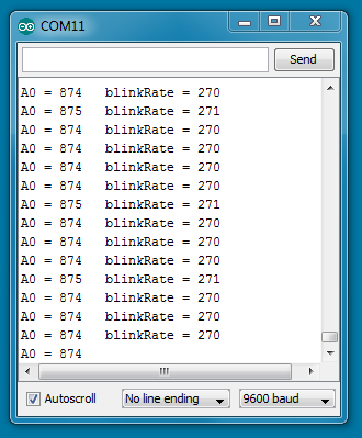
The following sketch is a slightly modified version of the example sketch AnalogReadSerial. Here the value of the pot is still read and echoed back to the serial monitor, but the value is also mapped from a minVal = 50 to a maxVal = 150 and this value is used to control the blink rate of an LED. Both the original and the mapped values are sent to the serial monitor.
The new Arduinio IDE has added a serial plotting utility.. Tools >> Serial Plotter

Using IF statements
Sometimes you would like to be able to have your sketch do different actions for different input conditions. This type of control can be accomplished using the if statement.
An if statement is a function that checks to see if a specified condition is true or false. IF the condition (known as a conditional) evaluates to be TRUE, the function executes a series of statements, IF the condition evaluates to FALSE, the function ends and the sketch skips the statements that belong to the IF function and moves to the next item in the sequence.
Here is an example of a CONDITIONAL...
int x = 5; // this is a statement that both defines and then sets the value of a variable
x == 0; // this is a conditional statement; the double equal sign is equivalent to asking the question
// is the current value of the variable x equal to zero? The answer to this question is NO or
// FALSE
the following is from the Arduino documentation pages and list some additional conditional statements.
x == y (x is equal to y)
x != y (x is not equal to y)
x < y (x is less than y)
x > y (x is greater than y)
x <= y (x is less than or equal to y)
x >= y (x is greater than or equal to y)
Conditional statements can be combined by including a logical AND (&&) or a logical OR ( || ), so the following statement can be used to define a range of values where a conditional will evaluate as TRUE.
x >= 10 && x <= 20 // True if x is equal to 10, 11, 12, 13, 14, 15, 16, 17, 18, 19 or 20
The if statement can now be used to turn on different light patterns depending on the value of the potentiometer. The following code shows how this functionality could be used to used LEDs to indicate the position of a "volume" dial.
Using Buttons statements - Digital Input
The digital I/O pins on the Arduino (pins 0 to 14) are referred to as I/O because they can they be configured as digital outputs - such as they have been used in the preceeding examples - and they can be configured to detect digital inputs. This means they can be used to detect when a voltage signal switches from a HIGH level (+5V) to a LOW level (0 V).
The button shown on the figure below has one leg connected to the GND pin on the Arduino and the other leg is connected to digital I/O pin 2. This setup can be used to set the button to be configured with a "pull-up" resistor - the typical circuit representation of this is shown in the figure to the right of the Fritzing diagram.
The purpose of the pull-up resistor is to allow the digital input pin to "see" a voltage level of +5V by pulling it up to this voltage level by means of a large resistor (typically greater than 10 kOhms). As long as the button is not pressed, the digital input pin reads +5V, but when the button is pressed the pin is connected directly to the ground pin and the digital input pin registers a digital LOW.
The Arduino contains built-in 20 kOhm pull-up resistors that can be engaged using the pinMode() function, this removes the need of having to include physical pull-up resistors in the circuit set-up. The pull-up resistor is set using the following statement in the setup() function:
pinMode( pin, INPUT_PULLUP);
The state of the input pin (HIGH or LOW or 1 to 0) is read using the digitalRead function
buttonState = digitalRead(pin);


The following sketch shows how to set up, read and display the state of the digital input pin. As long as the button is not pressed, the serial monitor will show that the state of the button is 1 (HIGH), when the button is pressed, the state of the button is switch to 0 (LOW).
Digital inputs such as buttons need to handled carefully when writing code. Mechanical buttons can "bounce" or "ring" when they are pressed and this can cause false readings - this leads to the concept of "debouncing" a button.
One also needs to decide when and how the code should react to different types of button actions, for example
- when the button is pushed
- when the button is released
- when the button is held down
This code sample is not commented - you should try adding in comments as you figure out what the code does...
***** Begin Sketch 8 *****
Things to try on your own...
- Use the code above to create a code that allows the button to be used to cycle through the LEDs. Press once for one LED, second press lights two LEDs, etc...
- Add a second button that only allows the LEDs to be changed by pressing button 1 when button 2 is held down.
- Obtain an LDR (light dependent resistor) and another potentiometer and use this to create an analog signal that is sensitive to light.
- Add a piezoelectric buzzer to the system and begin to explore the concept of PWM.
